

This open-source project lets AI generate editable CAD source code with one sentence, and can export STEP and URDF

3 months ago
Mechanical design is stuck again.
Using AI to generate a CAD model, but what you get is an STL mesh, and you can't change the hole positions.
To export the data as STEP format for factory use, you need to rebuild the geometry.
Robot description files require manually adding a lot of XML tags, which is error-prone.
Recently, I came across a project on GitHub called text-to-cad, which can generate CAD source code and engineering files with one click. These problems finally have hope.
It is an Agent-oriented CAD skill library with over 7400 stars on GitHub.
In a nutshell:
Use AI to write editable CAD source code and export it as engineering files like STEP, URDF.
Let me show you how convenient this thing is.
I want to design a robot chassis.
I casually opened ClaudeCode and said, "Generate a rectangular base with four mounting holes and two motor brackets."
It started writing Build123d Python source code.
Every geometric feature is defined with code:
hole positions, bracket sizes, base thickness.
Then it automatically exports a STEP file.
STEP can be directly imported into SolidWorks for editing.
Then it generates a URDF robot description.
It writes links, joints, and coordinate systems into XML, so ROS MoveIt2 can load it directly.
Throughout the whole process, I only said that one sentence.
The subsequent CAD modeling, URDF generation, and file export were all done by itself.
Some might wonder how it works.
01 Parametric CAD source code generation.
AI does not directly output a mysterious binary model.
It writes Build123d Python source code, and each geometric feature is marked with @cad[feature_name] references.
To modify a hole position, you only need to change the parameters in the source code, without redrawing the entire part.
The generated STEP file can be directly imported into professional CAD software for further editing.
02 Automatic generation of robot description files.
In URDF, error-prone parts like links, joints, limits are automatically written into XML.
Joint limits, coordinate systems, inertia parameters, etc., are validated for correctness.
With the CAD Viewer, you can view the robot structure locally without manually entering complex XML tags.
03 Built-in standard parts library.
Pick common standard parts like screws, bearings, motors from the step.parts catalog.
Unlike typical AI that fabricates non-standard screws.
In assemblies, it uses standard parts that can actually be purchased, avoiding the problem of "designed but can't buy the screw".
04 Local browser viewer.
WebGL renderer, runs natively in the browser, no need to install professional CAD software.
Supports formats like STEP, STL, URDF, with features like orbit rotation and component tree browsing.
You can see the generated parts on your phone, check the model without opening SolidWorks.
You can copy @cad[...] references to make subsequent edits based on specific geometric positions, rather than vague "the hole on the left".
Supports both orthographic and perspective projection, making it easy to observe from different angles.
The GLSL ray marching rendering mode is still experimental, but the native browser preview is already convenient enough.
05 DXF engineering drawings and G-code slicing.
Use 3D geometry projection to generate 2D DXF files for laser cutting and sheet metal processing.
Laser cutting service providers can receive the generated DXF files without opening AutoCAD to draw 2D drawings.
Sheet metal unfolding, gaskets, cutting layouts can all be automatically generated, saving the trouble of manual drawing.
Templates, gaskets, cutting layouts can all be automatically generated, no need to manually draw 2D outlines.
Supports real slicer CLI to generate printer-specific G-code, 3D printing can be initiated directly from G-code.
Bambu Labs printers can be directly connected to initiate print jobs from validated G-code.
SendCutSend sheet metal processing can do pre-order file checks to prevent format errors, oversized dimensions, etc.
The entire manufacturing process from CAD modeling to cutting and printing can be automated. If you want to see it, just try it.
If you want to try, installation is simple
Skills CLI Installation:
npx skills install earthtojake/text-to-cad
Claude Code Plugin Installation
claude plugin marketplace add earthtojake/text-to-cad

claude plugin install cad@text-to-cad
Python CAD Environment
python3.11 -m venv .venv

./.venv/bin/pip install -r requirements-cad.txt
Viewer Frontend
npm --prefix viewer install

npm --prefix viewer run dev
Open http://localhost:4178 to see the generated model.
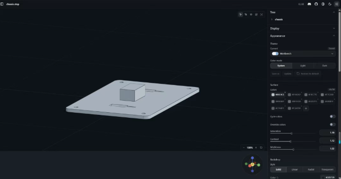
After installation, if you want to see the effect, just try it directly.
Here are some limitations to mention
Implicit CAD is still experimental and incomplete.
Viewer development requires Node environment, which is a barrier for those who only use Python.
Git LFS assets are not pulled by default, need to manually:
git lfs pull --include="benchmarks/**"
No Chinese documentation, README and SKILL.md are in English.
No verification of complex assembly generation effects, only single part benchmarks done so far.
Commercial licenses for OpenCascade and step.parts libraries need to be checked yourself.
I think the approach of text-to-CAD is correct.
Let AI directly generate CAD source code, then export engineering files, rather than hiding in a black box model.
When modifying a hole, you don't need to redraw the entire part.
Dimensions, datums, assembly relationships are all in the code, clear at a glance.
But if you only need a pretty 3D image, there's no need to use it.
Its greatest value is to connect the chain of "natural language → CAD → robot description → manufacturing files".
If you need it, go ahead and try it.
The project is open under the MIT license. Interested students can check out the source code and documentation on the GitHub repository.
Open source address:



Wow, after struggling with AI parametric modeling for half a month and almost giving up, I finally see hope again.